The tube is particularly suitable for single-sideband and linear amplifiers.

| GENERAL DESCRIPTION |
|
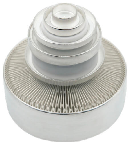
The RS 1072 C / FU115F is a forced air-cooled, metal-ceramic tetrode for frequencies up to 300 MHz, output power approx. 1 kW. The tube is particularly suitable for single-sideband and linear amplifiers. |
|
| TECHNICAL SPECIFICATIONS | ||||
| HEATING | ||||
| Heater voltage | 3.8 V ±5% | |||
| Heater current | 20.5 ±2 A | |||
| Preheating time | > 3 min | |||
| Type of heating | indirect by ac or dc | |||
| Cathode | matrix oxide | |||
| CHARACTERISTICS | ||||
| μ-factor of grid 2 | ±11 | |||
| Transconductance | ±43 mA/V | |||
| CAPACITANCES | ||||
| min | nom | max | ||
| Cathode/grid 1 | 32 | 36 | 39 | pF |
| Cathode/grid 2 | 1.2 | 1.5 | 1.8 | pF |
| Cathode/plate | 0.015 | pF | ||
| Grid 1/grid 2 | 50 | 57 | 65 | pF |
| Grid 1/plate | 0.15 | pF | ||
| Grid 2/plate | 12 | pF | ||
| Specifications may change without notice | ||||
| THIS TUBE IS USED IN THE FOLLOWING SHORTWAVE BROADCAST TRANSMITTERS | ||
| Manufacturer | Transmitter specifications | Power in kW |
| RIZ Transmitters | OR 50 K-01/A | 50 |
| OR 100 K-01/A | 100 | |
| Siemens | WR Send 50 K-04 | 50 |
| WR Send 100 K-04 | 100 | |
| THIS TUBE IS AVAILABLE FROM | ||
| Manufacturer | Rebuilder | Distributor |
| Xuguang | Kennetron | |
| PRICE LEVEL (US$) | |||||
| 1 | 2 | 3 | 4 | 5 | 6 |
| 0 - 10 | 10 - 100 | 100 - 1000 | 1000 - 10,000 | 10,000 - 50,000 | 50,000 - 100,000 |